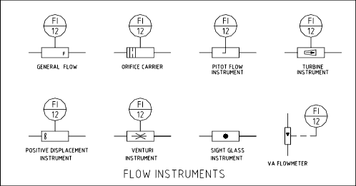
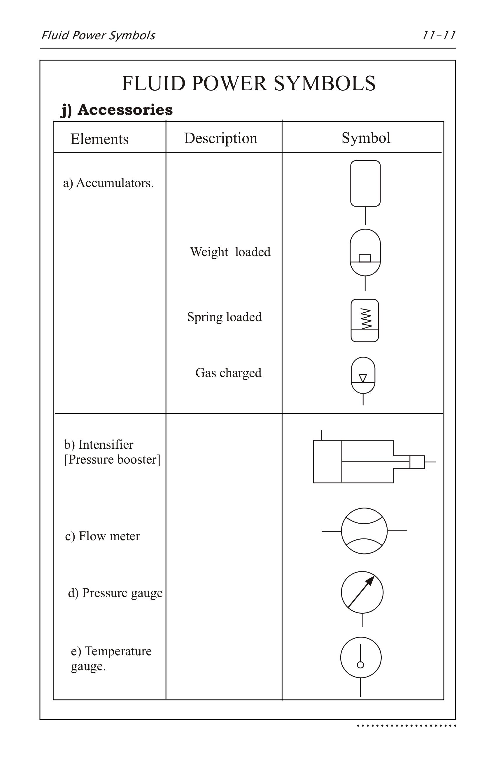
hydraulic flow meter symbol
Upper right quadrant of 1. Density is defined as the mass per unit volumeIt is an intensive property which is mathematically defined as mass divided by volume.

Hydraulic Symbology 305 Condition Monitoring Symbols
GEOLOGICAL SURVEY Open-File Report 88-707 Reston Virginia 1988.
. Turn the dial on the multimeter so it points to the continuity setting which looks like 5 curved vertical lines. Warnings found in this manual outside of this section are designated with the warning symbol. A shock hazard warning refers to a risk of a possibly severe electrical shock due to improper use or handling of the equipment.
If I have a hydraulic drill press when flow is turned on to the top side perhaps I have a clamp that I want to engage first. Figure 1 shows the symbols that depict the major valve types. Propeller-type current meters similar to the purely mechanical Ekman current meter but now with electronic data acquisition can be traversed over the area of the penstock and velocities averaged to calculate total flow.
Does not include engine fuel flow or pressure. The number of vortexes that form within a given time period. In words the density ρ of a substance is the total mass m of that substance divided by the total volume V occupied by that substance.
Flow through a large penstock such as used at a hydroelectric power plant can be measured by averaging the flow velocity over the entire area. I - AI airborne interceptors prioritized. Hydraulic Hand Pump.
Given the soils saturated hydraulic conductivity K s 5 mmhr find. Absolute thermal resistance is the temperature difference across a structure when a unit of heat energy flows through it in unit timeIt is the reciprocal of thermal conductanceThe SI unit of absolute thermal resistance is kelvins per watt KW or the equivalent degrees Celsius per watt CW the two are the same since the intervals are equal. ΔT 1 K.
The mass air flow meter. Jobson and David C. Electro-Hydraulic Valve Spring Gate Valve Balanced Diaphragm Gate Valve Slide Valve Metering Coke Post Indicator Knife Valve Diaphragm Valve Excess Flow Valve Self Draining Valve Pinch Valve Minimum Flow Valve Auto Recirculation Gauge Bleeder Valve Integrated Block Valve Maual Integrated Valve Orifice Rotameter Quarter Turn Valve Double Acting Quarter Turn Valve Spring.
The magnitude of pressure developed by the vortexes that form C. This type of flow meter entraps a known quantity of fluid per pulse and by totaling up the pulses over time the fluid flow rate is known. VOLUME 1 -- HYDRAULIC CHARACTERISTICS OF OPEN CHANNELS By JC.
DEPARTMENT OF THE INTERIOR DONALD PAUL HODEL Secretary US. SystemStak symbol has the same basic form and size as shown in fig. LaGrega and Keenan2 investigated the effect of flow equalization at the 18-mgd Newark NY Wastewater Treatment Plant.
For saturated flow testing methods there is quite a variety of techniques that. It is only after enough pressure is built that the motor would turn. Close Log In.
For clarity directional valves are drawn vertically in SystemStak circuit diagrams see fig. Remember me on this computer. GEOLOGICAL SURVEY Water-Resources Investigations Report 86-4127 Prepared in cooperation with FEDERAL HIGHWAY ADMINISTRATION o i o 00 Sacramento California 1986.
In a vortex flow meter the sensor placed downstream measures _____. For ease of understanding remember the directions of flow for each line and that all four flow paths pass through each valve see fig. N - Normal priority.
An existing aeration tank was temporarily converted to an. A flow control valve is used for adjusting the flow rate of a fluid in a pipeline. The circuit in Figure 5-4 shows a meter-in flow control at each directional control valves inlet to control speed in both directions.
Flow controls are usually required to keep single cylinder movement from over speeding. A constant water pressure of was maintained at the bottom of a 05 m vertical saturated soil column and the water height at the columns top was also kept constant at 20 mm. Constant pressure that is proportional to flow rate B.
In such cases information concerning the valve type may be conveyed by the component identification number or. Placing flow controls at the cylinder ports would allow separate speeds for extension and retraction. Chief Office of Surface Water US.
Valves are used to control the direction flow rate and pressure of fluids. Enter the email address you signed up with and well email you a reset link. 1 The direction of flow.
A constant influent feed rate also avoids hydraulic disruptions in the clarifier created by sudden flow changes especially those caused by additional wastewater lift pumps suddenly coming on line. The valve contains a flow passage or a port whose area can be varied. It should be noted that globe and gate valves will often be depicted by the same valve symbol.
Shows symbol indicating type of threats selected to be shown. The FA20D engine used a hot-wire slot-in type air flow meter to measure intake mass this meter allowed a portion of intake air to flow through the detection area so that the air mass and flow rate could be measured directly. Draw a system sketch and a potential.
High engine speeds and loads. Indicates if limited mode is selected. Peck Director For additional information write to.
Function Basic symbol Basic model Features Page Relief DGMCDCMC2 Single dual and crossport 5 models Reducingrelieving DGMX2 Piloted from and reduced 13 pressure in port P A or B Sequence DGMR1 Single port P sequence 17 Counterbalance DGMR Control in port T 20 Flow Control DGMFN Single or dual port meter-in 24. What is Density Typical densities of various substances at atmospheric pressure. System status circle area II.
A warning is a statement that identifies conditions or actions that could result in personal injury or loss of life. Each station valve stack is a combination of functions. LJnsaturated Flow The situation for unsaturated hydraulic conductivity is much more complex than for saturated flow because the purpose is to determine a complete hydraulic conductivity function over a range of water contents or pressure heads rather than just one point as for saturated flow.
If you want to measure the ohms use the multimeter setting that has the omega symbol Ω. BASIC HYDRAULIC PRINCIPLES OF OPEN-CHANNEL FLOW By Harvey E. A Textbook of Fluid Mechanics and Hydraulic Machines by R.
U - Unknown emitters prioritized. Port injection and direct injection for high fuel flow volume. Includes pressure warning systems for pumping systems within the tank etc.
F - Friendly emitters shown in addition to other threats. Symbol Of Flow Control Valve Used In Hydraulic System Circuit Diagram. The arrows point into the symbol indicating the direction of heat flow.
General symbol push knob push-pull knob single pedal double acting pedal plunger plunger with stroke limitation spring roller lever wrrh roller single solenoid pushpull solenoid direct pilot operated pneumatic hydraulic operated electric motor other control unit not electric motor intermediate position proportional spool coupling internal pilot external pilot directional valve. Saturated Flow and Potential Diagram. In a schematic diagram the switch symbol appears to be a toggle switch with a flag hanging below.
If mass flow rate outputs are required then the positive displacement flow meter requires other readings to infer mass flow. I could connect the cylinder to the top side line and the cylinder would clamp in order to build up pressure. Those units and components which furnish hydraulic fluid under pressure includes pumps regulators lines valves etc to a common point manifold for redistribution to other defined systems.
Manual or computer calculations incorporating physical process measurements such as absolute pressure. GEOLOGICAL SURVEY Dallas L. Log in with Facebook Log in with Google.
The schematic diagram of course only shows the circuitry and not the pipe where the switch is physically mounted. UNITED STATES DEPARTMENT OF THE INTERIOR DONALD PAUL HODEL Secretary GEOLOGICAL. Before you test the fuse put the positive and negative leads together and listen for the meter to beep to ensure its working properly.
This particular flow switch is used to trigger an alarm light if coolant flow through the pipe ever falls to a dangerously low level and the contacts are. Symbol Of Pressure Control Valve Used In Hydraulic System Circuit Diagram. A - AAA anti-air artillery prioritized.
Hydraulic Circuit Schematic Showing The Location Of The Flow Meter Used Download Scientific Diagram

A Guide To Common Hydraulic Symbols Engineeringclicks
Symbols And Parts Introduction Hydrotech

Hydraulic Symbology 205 Hydraulic Pumps

Hydraulic Symbols Zeus Hydratech
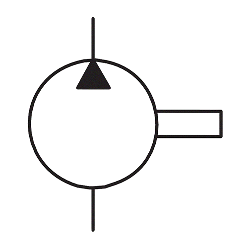
Hydraulic Symbols Zeus Hydratech

Fluid Power Symbols Ppt Download
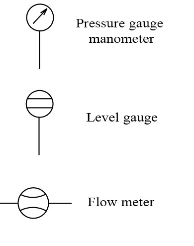
How To Read Hydraulic Circuits Schematic Hydraulic Symbols To Din Iso 1219
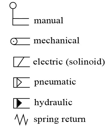
How To Read Hydraulic Circuits Schematic Hydraulic Symbols To Din Iso 1219

Common P Id Symbols Used In Developing Instrumentation Diagrams Learning Instrumentation And Control Engineering

Hydraulic Symbology 305 Condition Monitoring Symbols

Hydraulic Symbols Piping And Tubing Symbols Normal Working
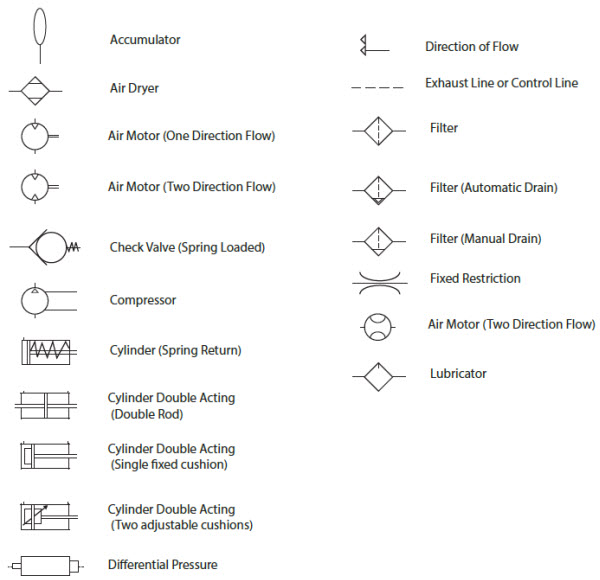
Pneumatic Circuit Symbols Explained Library Automationdirect
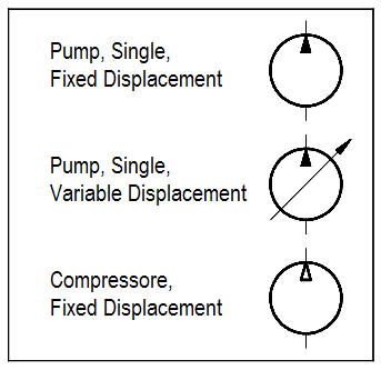
Hydraulic And Pneumatic P Id Diagrams And Schematics Inst Tools
